LIGHT KIT INSTRUCTIONS
Step by Step Instructions
Table of Contents
0. Foreword
1. Opening up the Diecast
2. Attaching Windshield Glass
3. Drilling Out Holes for Lights
4. Pre-Resin Drilled Holes
5. Placing and Curing the LEDs
6. Making Room for the PCBA - Seat Cutout
7. Locating and Drilling the Power & Button Hole
8. Solder Power Wires
9. Functionality Test
10. Attaching PCBA to Chassis
11. Closing up the Diecast
12. Plug your Diecast and Enjoy
Foreword
The following are the steps and general guidelines to follow for typical diecast structures. However, each diecast will require a bit of creativity and ingenuity to work with its unique design. That’s the fun of diecast customization!
Note: These generic instructions additionally assume you have a subset of materials already to work with. These are outlined in the Tools and Materials section of this guide. Use your creativity and intuition to adapt these instructions to other materials you may have on hand or prefer to use.
Step 1: Opening up the Diecast
Begin by drilling the center of each rivet slowly and steadily. A good bit size is typically 3/16, although the rivet size may vary from diecast to diecast. Start at a low drill speed to maintain control. Keep the drill bit perpendicular to the rivet to ensure an even, straight hole.
Note: Drilling the rivets creates a lot of metal shavings. Make sure that your Diecast EV electrical components are protected from the shavings, as they can cause shorts in the circuitry.
If the rivets are drilled out properly, the individual parts of the diecast vehicle should now separate easily.

Step 2: Attaching Windshield Glass
Grab the diecast body and the glass and fit them together. Note areas where the glass touches the metal body and are not visible from the exterior of the diecast vehicle. Put a droplet of clear resin in the noted spot(s) and attach the glass to the body. Use a UV light to cure the resin.
Note: Always make sure you have proper ventilation when working with resin.

Step 3: Drilling Out Holes for Lights
This is where the fun begins. Assess the vehicle structure externally & internally to decide where you will be placing the lights. Pay close attention to the path that the LED wires will have to take back towards the center of the diecast.
Drill each LED hole, one at a time. Once again, make sure that none of the electronics are around while drilling as to prevent metal shavings from landing on those components.
Pro Tip: In some diecasts it is not very intuitive where the turn signals should be placed. This is because often in the vehicle that inspired the design the turn signal is integrated into the same headlight assembly. In these scenarios you can drill a single hole and both the headlight and turn signal light will use the same light channel.

Step 4: Pre-Resin Drilled Holes
Carefully dab uncured resin into one of the drilled LED holes, being careful not to push it completely out on the other side. The surface tension of the resin will typically create nice rounded and smooth looking headlight from the outside. DO NOT insert the LED yet. Cure the resin in each of the drilled holes.
Repeat this step with each LED hole before moving on to the next step.

Step 5: Placing and Curing the LEDs
Now you can begin to place and cure each light, one at a time. Dab a small amount of resin on top of the already cured resin in one LED hole. Lightly insert the LED into the uncured resin. Use the UV light to cure the LED and secure it in place. Add and cure another small dab of resin behind the attached LED. This protects the wire from ripping out of the LED in future steps when you will be handling the wires. Repeat with each LED.
Pro-tip: LEDs have a direction in which they are brighter. LEDs are built with a lens on one side. Make sure that this lens is facing outward as you cure the resin.

Step 6: Making Room for the PCBA - Seat Cutout
Pro-Tip: Trimming the installed LED wires down to a more reasonable length will help keep the mess in order a little bit more and make it easier to handle this fit next step
In the majority of cases it is not possible to have the seats, PCBA, and lights fit without modifications to the seat piece. We suggest that you cut out and toss the center portion of the seats and only retain and install the front and back end sections. Those front and back end sections of the seat piece stabilize the wheel shafts in place when the entire diecast is closed up.
Place the remaining pieces back into the diecast structure and lightly glue them with resin. Proceed to do a fit test with the PCBA in place (note that we are not soldering anything yet, we are simply checking PCBA fit) and the diecast chassis to make sure that all pieces will play nice with each other. Continue to cut out plastic parts until proper fit is achieved. At this point you can open up the pieces back up and permanently attach the wheel stabilizer sections into the diecast body with resin.

Step 7: Locating and Drilling the Power & Button Hole
Dry fit the PCBA back into the chassis piece. Take note of the general location of where the power connection and the button land. Remove PCBA and place in an area that can remain clean.
Use a drill bit to open up a hole that will allow passthrough of the power cables and access to the button through the chassis.
Pro Tip: Drill bit size of 5/16 - 3/8 tends to work best.

Step 8: Soldering LEDs
Carefully remove ~5mm of the insulation on each LED wire.
Pro Tip: This can be done in many ways but by far the easiest method is to purchase a wire striper small enough for these wires. See Tools and Materials Section for an example.
The PCBA has text written next to each hole that defines the function of that hole. Insert one wire at a time into the correctly labeled hole in the PCB and solder the wire. Note that the LED wires are color coded so that you can easily locate what wire pertains to what light.
| LED Color | Function | Polarity Description |
| Red | Tail Lights | Red wire (+), Black wire (-) |
| White | Head Lights | White wire (+), Black Wire(-) |
| Orange | Turn Signals | Yellow wire (+), Black wire(-) |
For the black wires (aka. ground/negative) the hole in which they are soldered to does not matter, as long as the hole is labeled (-) negative.

Note: The wire colors in the GIF above are not color representative of the latest design. Follow the colors in the table and diagram below.

Step 8: Solder Power Wires
Near the center of the PCBA next to the button you will find power ports. There are the power input pins for the PCBA. Using the provided wires, solder the positive wire and negative wire accordingly by following the polarity markings printed onto the circuit board
Step 9: Functionality Test
Attach the power wires to the barrel adapter provided in the kit. Connect the barrel adapter to the AC adapter (aka wall wart) and plug it into a wall socket. Check that all LEDs are turning on and that the button toggles the LEDs through the lighting patterns. If any of the LEDs are not turning on then a wire has not been soldered properly. Desolder the positive and negative wires of that LED, make sure insulation is properly removed and try to solder again. Once all LEDs are functioning correctly you can move on to the next step.

Step 10: Attaching PCBA to Chassis
To make sure that the button can be easily pressed, place the fully soldered PCBA into the chassis such that the power wire and button are passing through the chassis pass-through. To do this you will need to remove the barrel adapter from the previous step and pass the power wire through the pass-through hole.
While holding the PCBA firmly, dab some resin into the edges of the board so that once cure the resin will hold the PCBA firmly to the chassis. Cure the resin. Keep adding resin and curing it all around the board until the PCBA is firmly held down.
Step 11: Closing up the Diecast
Close up the diecast by placing the Chassis + PCBA assembly into the Body Assembly. Flip the diecast upside down so that the chassis is visible. Dab some resin in the holes where rivets used to hold the chassis down. Firmly press the chassis into the body and cure the resin.

Step 12: Plug your Diecast and Enjoy
Attach the power wires to the barrel adapter previously used in the functionality check step. Connect the barrel adapter to the AC adapter (aka wall wart) and plug it into a wall socket.
The build is now complete!

Warnings
- Proper ventilation should be used for soldering
- Proper ventilation should be used for using and curing UV resin
-
Proper care should be taken when using resin and UV lights. PPE is recommended to protect skin from the resin and eyes from the UV light.
Recommended Tools and Materials:
- UV Resin
- Wire Stripper
- Solder Iron
- Solder Iron AC Adapter
- Solder Wire
- Drill + drill bits
- Precision Screwdriver
- UV Light Safety Glasses
- Nitrile Gloves
Reference Image: Diecast Exploded View
Watch a Full step by step Video on Youtube here.
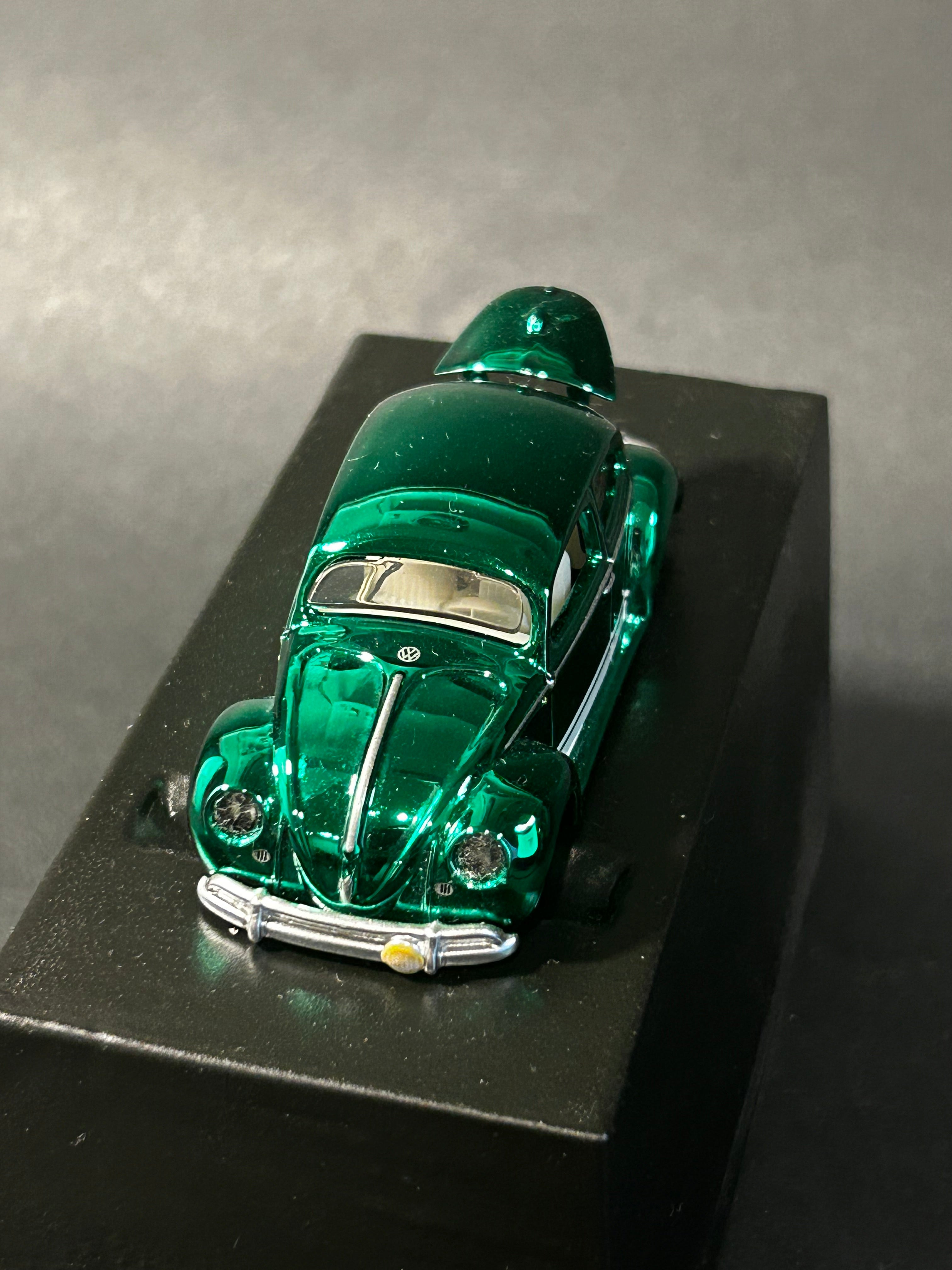
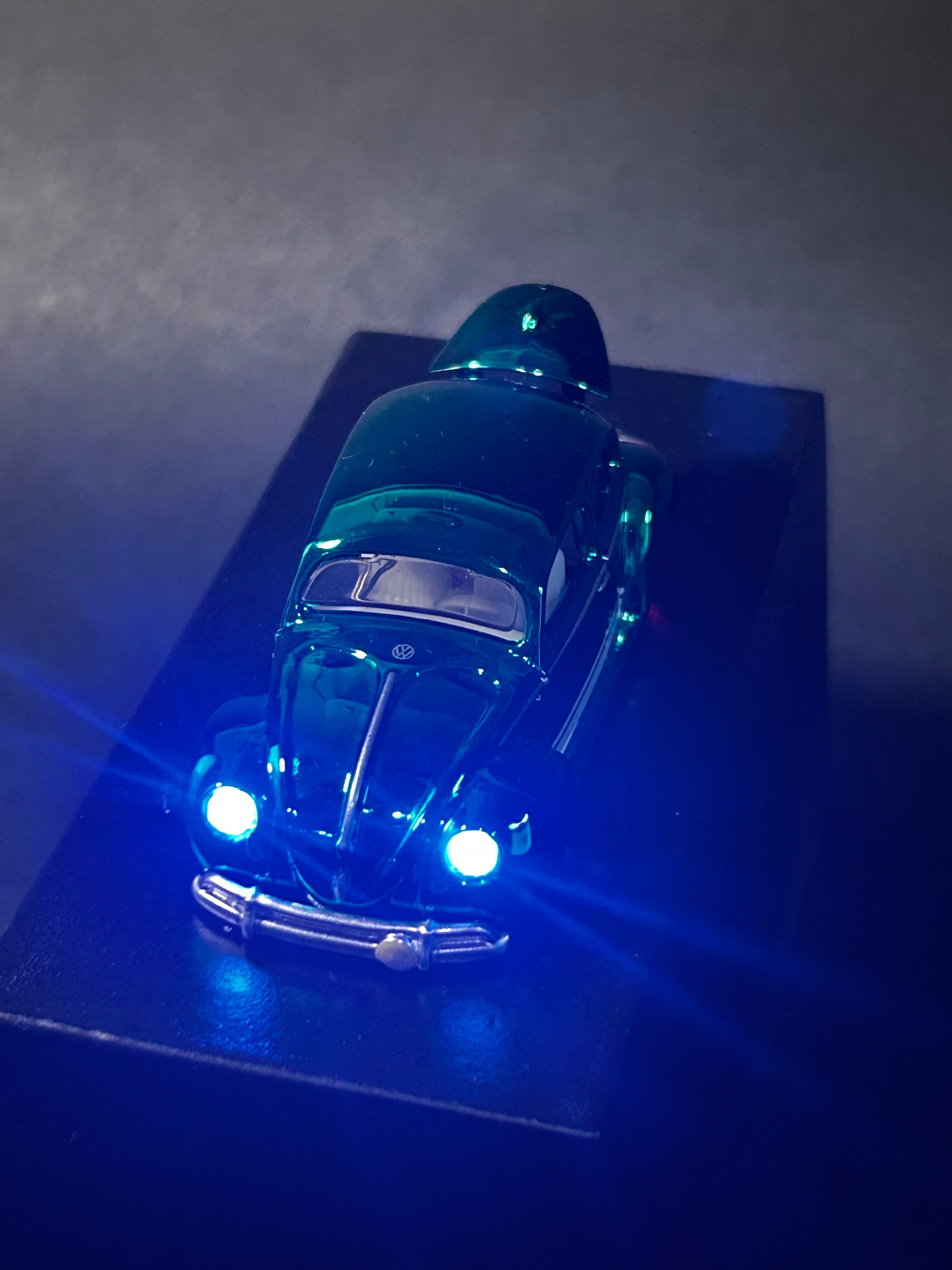
Before/After
Kawa-Bug-A (Green)